Lityum pil katot malzemelerinin ince öğütme işleminde, jet değirmenleri ve mekanik değirmenler yaygın olarak kullanılan ekipmanlardır. Öğütme prensipleri ve etkinlikleri bakımından önemli farklılıklar gösterirler. Ürün özelliklerini, kalite gereksinimlerini ve enerji tüketimi hedeflerini karşılamak için uygun öğütme ekipmanının seçilmesi ve malzeme özelliklerine göre işlem parametrelerinin optimize edilmesi çok önemlidir.
Bu makale, başlığı şu şekildedir: “Ekipman Odak Noktası: Performans Karşılaştırması” Jet Değirmeni İnce öğütme için mekanik değirmen ile karşılaştırma”, Aşağıdaki bölümleri kapsamaktadır:
1. Jet Değirmeni
Burada bahsedilen jet değirmeni, akışkan yataklı bir jet değirmenidir. Sistem ekipman akışı Şekil 1'de gösterilmiştir.
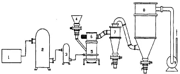
1 – Hava Kompresörü, 2 – Hava Tankı, 3 – Soğutma ve Arıtma Sistemi, 4 – Besleme Sistemi, 5 – Öğütme Mekanizması, 6 – Yatay Sınıflandırma Mekanizma, 7 – Siklon Sınıflandırma Sistemi, 8 – Filtre Sistemi, 9 – Emme Fanı
Şekil 1: Jet Değirmeni Sistemi Ekipman Akış Şeması
Soğutulmuş, filtrelenmiş ve kurutulmuş sıkıştırılmış hava, iki veya üç boyutlu olarak düzenlenmiş çeşitli nozullar aracılığıyla öğütme odasına enjekte edilerek süpersonik hava akışı oluşturur. Bu jetin kinetik enerjisi malzemeyi akışkanlaştırır. Hızlandırılmış parçacıklar, nozul jetlerinin kesişme noktasında birleşerek yoğun çarpışma, sürtünme ve kesme kuvvetlerine maruz kalır ve ultra ince öğütme sağlanır. Öğütülmüş malzeme daha sonra yükselen hava akışı ile sınıflandırma bölgesine taşınır. Merkezkaç kuvveti altında... sınıflandırıcı Tekerlek ve fanın emme kuvveti sayesinde iri ve ince parçacıklar ayrılır. İri parçacıklar yerçekimi nedeniyle öğütme haznesine geri düşerek daha fazla öğütülür. Boyut gereksinimini karşılayan nitelikli ince parçacıklar, hava akımıyla birlikte siklon ayırıcıya girerek daha fazla ayrıştırma ve toplama işlemine tabi tutulurken, malzemedeki ince parçacıklar toz toplama sistemine gider.
Jet öğütme işleminde, temel ekipman parametreleri şunlardır: Meme çapı, ilerleme hızı, taşlama basıncı, sınıflandırıcı tekerleğin doğrusal hızı ve hava emme hacmi. Bunlar birlikte ürün özelliklerini, kalitesini ve üretimini etkiler.
(1) Meme
Jet değirmenlerinde kullanılan nozul, İsveçli mühendis Gustaf de Laval tarafından icat edilmiştir ve bu nedenle jet değirmenlerinde kullanılan nozul olarak adlandırılır. “Laval nozulu”. Ön kısmı genişten dar bir boğaza doğru daralır ve daha sonra küçükten büyüğe doğru genişler. Bu yapı, hava akış hızının (v) nozulun kesit alanıyla değişmesine neden olarak, hava akışını ses altı hızlardan ses hızlarına ve nihayetinde ses üstü hızlara doğru hızlandırır.
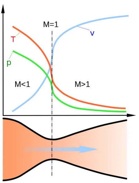
Şekil 2: Laval Nozulunun Şematik Diyagramı
Sıkıştırılmış hava, nozülden geçtikten sonra süpersonik hale gelir ve öğütme haznesine girer. Hava akışı ve malzemenin etkisi göz önüne alındığında, nozülün yüksek mekanik dayanım ve aşınma direncine sahip olması gerekir. Şekil 3a'da gösterildiği gibi, paslanmaz çelik bir nozül bir aylık kullanımdan sonra ciddi aşınma gösterir. Bu aşınma, hava akışı alanını bozarak öğütülmüş ürünün partikül boyutunu ve özgül yüzey alanını etkiler ve ayrıca metal kirliliğine neden olarak ürün kalitesini düşürür. Bu sorunlardan kaçınmak için, Şekil 3b'de gösterildiği gibi, seramik nozüller günümüzde yaygın olarak kullanılmaktadır.
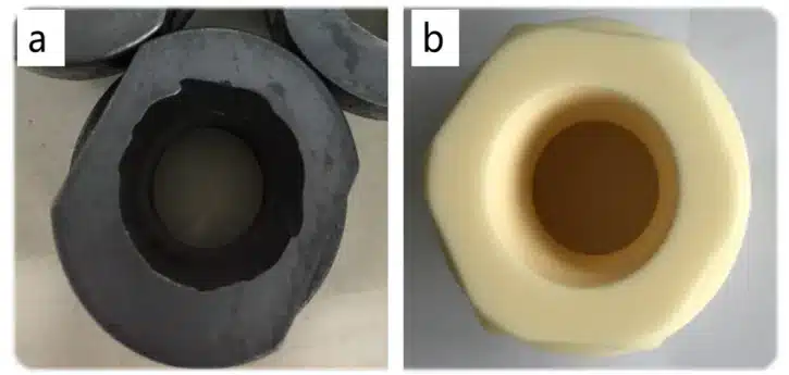
Şekil 3. a Paslanmaz çelik nozul b Seramik nozul
(2) Sınıflandırıcı Çarkı
Sınıflandırma çarkı, ön flanş, arka flanş, çok sayıda bıçak ve hava sızdırmazlık diskinden oluşur. Bitişik bıçaklar arasındaki boşluklar besleme kanalları görevi görür ve bıçakların iç tarafları bir boşluk oluşturur. Sınıflandırma çarkının doğrusal hızının artması, ürün parçacık boyutunun küçülmesine neden olur. Doğrusal hız, hem sınıflandırıcı tekerleğin çapı hem de dönüş hızıyla pozitif korelasyon göstermektedir. Taşlama haznesindeki malzeme yükü, sınıflandırıcı tekerlek motorunun akımı aracılığıyla izlenebilir; daha yüksek akım, haznede daha fazla malzeme olduğunu gösterir.
Malzeme, sınıflandırıcı tekerleğe çarparak darbe indirir. Şekil 4a/b'de görüldüğü gibi, paslanmaz çelik sınıflandırıcı tekerlekler uzun süreli kullanımdan sonra aşınma gösterir. Bunu önlemek için, Şekil 4c'de gösterildiği gibi, seramik sınıflandırıcı tekerlekler artık yaygın olarak kullanılmaktadır.
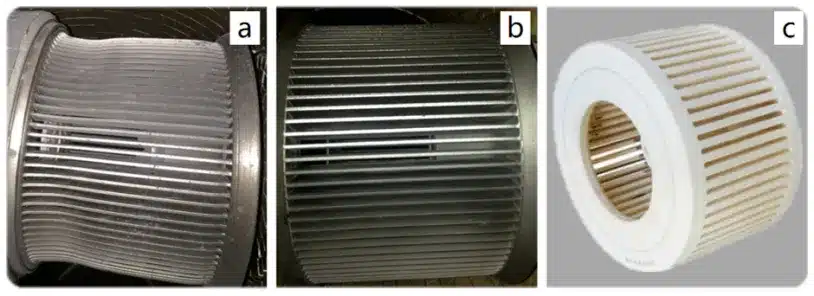
a. Paslanmaz Çelik Malzeme (Aşınmış), b. Paslanmaz Çelik Malzeme (Normal), c. Seramik Malzeme
Şekil 4. Sınıflandırıcı Çarkı
(3) Ürün Özellikleri
Jet değirmeni parametreleri ile ürün partikül boyutu/çıktısı arasındaki ilişki aşağıdaki gibidir:
- “—” Bu, nozul çapı ile parçacık boyutu arasında doğrudan bir ilişki olmadığını gösterir.
- “↗” Bu, parametre arttıkça ürün özelliklerinin de arttığını gösterir.
- “↘” Bu, parametre arttıkça ürün özelliklerinin azaldığını gösterir.
Not: Her parametrenin etki ağırlığı farklılık gösterir.
| Gösterge/Parametre | Meme çapı | Besleme Hızı | Taşlama Diski Doğrusal Hızı | Sınıflandırıcı Çark Doğrusal Hızı | Emme Çekiş Seviyesi |
| Parçacık Boyutu | — | ↘ | ↘ | ↘ | ↗ |
| Üretim kapasitesi | ↗ | ↗ | ↗ | ↘ | ↗ |
Parametre Ayarlama Süreci:
- Ekipman modeline ve tahmini kapasiteye göre nozul boyutunu önceden seçin.
- Malzemenin hedef partikül boyutuna bağlı olarak uygun doğrusal hız aralığını (sınıflandırıcı tekerlek devir sayısı) belirleyin.
- Malzeme özelliklerine (örneğin, tek kristalli, çok kristalli, sert aglomere, yumuşak aglomere) bağlı olarak uygun bir öğütme basıncı aralığı belirleyin. Aşırı basınç, uzaklaştırılması zor olan aşırı miktarda ince parçacık oluşmasına neden olur.
- Kapasite gereksinimlerine göre besleme hızını ve hava emme hacmini optimize edin.
- Son kapasite ve enerji tüketimine bağlı olarak nozul çapının optimize edilip edilmeyeceğini yeniden değerlendirin.
2. Mekanik Değirmen
Burada ele alınan mekanik değirmen, mekanik darbeli bir değirmendir. Sistem ekipman akışı Şekil 5'te gösterilmiştir.
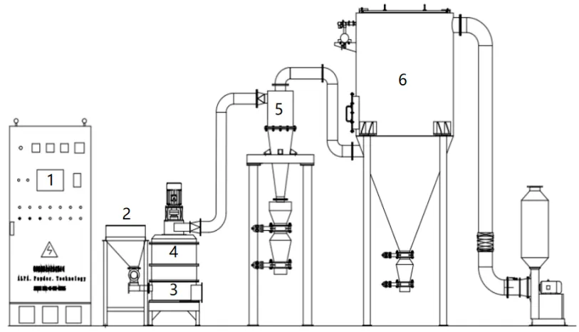
1- Elektrik Kontrol Kabini, 2- Besleme Sistemi, 3- Öğütme Mekanizması,
4- Sınıflandırma Mekanizması, 5- Siklon Ayırma Sistemi, 6- Filtre Sistemi
Şekil 5. Mekanik Değirmen Sistemi Ekipman Akış Şeması
Malzeme, bir besleme sistemiyle öğütme haznesine eşit şekilde beslenir ve burada yüksek hızda dönen bir öğütme diskinin güçlü darbesine maruz kalır. Eş zamanlı olarak, merkezkaç kuvveti malzemenin öğütme halkasıyla çarpışmasına neden olur ve boyut küçültme için kesme, sürtünme ve darbe kuvvetlerinin birleşimiyle oluşur. Öğütülmüş malzeme, kaba ve ince parçacıkların ayrılması için hava akımıyla sınıflandırma bölgesine taşınır. Kaba parçacıklar daha fazla öğütme için öğütme haznesine geri döner. Nitelikli ince parçacıklar, daha fazla ayırma ve toplama için hava akımıyla siklon ayırıcıya girerken, ince parçacıklar toz toplama sistemine gider.
Mekanik değirmen için temel ekipman parametreleri şunlardır: besleme hızı, taşlama diskinin doğrusal hızı, sınıflandırıcı tekerleğin doğrusal hızı ve hava emme hacmi, Bu faktörler, ürün özelliklerini, kalitesini ve üretimini birlikte etkiler.
(1) Taşlama Diski
Taşlama diski, taşlama pimleriyle donatılmıştır. Haznedeki malzeme, bu yüksek hızlı dönen pimler tarafından darbe alır. Şekil 6a, uzun süreli çalışma sırasında aşınmaya eğilimli olan ve metal kirliliğine yol açan metal bir taşlama diskini göstermektedir. Günümüzde yaygın olarak seramik taşlama diskleri kullanılmaktadır. Daha sert ve aşınmaya daha dayanıklı olmalarına rağmen, kırılgan yapıları genellikle metal disklere kıyasla daha düşük bir doğrusal çalışma hızı gerektirir ve bu da darbe kuvvetini bir miktar azaltır. Daha yüksek taşlama diski doğrusal hızı, daha küçük ürün parçacık boyutuna yol açar. Doğrusal hız, hem disk çapı hem de dönme hızıyla pozitif bir korelasyon göstermektedir.
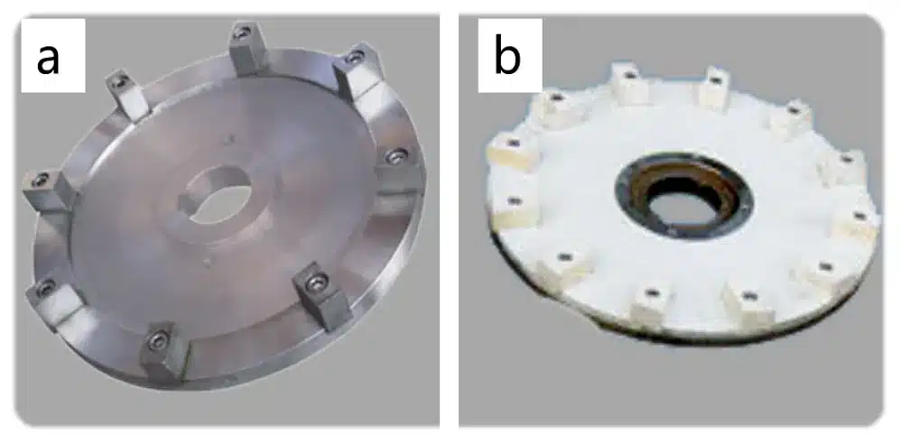
Şekil 6. a. Metal Taşlama Diski b. Seramik Taşlama Diski
(2) Ürün Özellikleri
Mekanik öğütme parametreleri ile ürün partikül boyutu/üretimi arasındaki ilişki aşağıdaki gibidir:
- “—” Besleme hızı ile parçacık boyutu arasında doğrudan bir ilişki olmadığını gösterir.
- “↗” Bu, parametre arttıkça ürün özelliklerinin de arttığını gösterir.
- “↘” Bu, parametre arttıkça ürün özelliklerinin azaldığını gösterir.
Not: Her parametrenin etki ağırlığı farklılık gösterir.
| Gösterge/Parametre | Besleme Hızı | Taşlama diskinin doğrusal hızı | Sınıflandırıcı Çark Doğrusal Hızı | Emme Çekiş Seviyesi |
| Parçacık Boyutu | — | ↘ | ↘ | ↗ |
| Üretim kapasitesi | ↗ | ↗ | ↘ | ↗ |
Mekanik bir değirmende sınıflandırıcı çark ve diğer parametrelerin ayarlanma süreci, jet değirmenindekine benzer.
(3) Performans Karşılaştırması
Jet değirmenleri ve mekanik değirmenlerin farklı öğütme prensipleri, bunların uygulanabilirliğini, verimliliğini ve enerji tüketimini belirler. Temel olarak:
- Jet Değirmenleri Parçacıkların boyutunu küçültmek için süpersonik hava akımı kullanılarak parçacıklar arası çarpışmalar meydana getirilir.
- Mekanik Değirmenler Şekil 7'de gösterildiği gibi, boyut küçültme amacıyla, dönen bir disk kullanılarak malzeme sabit pimlere ve hazne duvarına doğru fırlatılır.
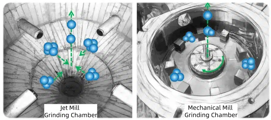
Şekil 7: Jet değirmeni / Mekanik değirmen haznelerinde parçacık boyutunun küçültülmesinin şematik diyagramı
| Jet Değirmeni | Mekanik Değirmen | |
| Prensip | Süpersonik hız, malzemeler arasında çarpışmalara neden olur. | Malzeme ve Ekipman Arasındaki Kesme ve Çarpışma |
| Öğütme Yoğunluğu | Büyük: Süpersonik hız | Küçük: Taşlama diskinin doğrusal hızı sınırlıdır. |
| Enerji Tüketimi | Yüksek: Basınçlı hava gereklidir | Düşük: Soğutma için dolaşımdaki suyu kullanır. |
| Maliyet | Yüksek | Düşük |
| Ekipman Ayak İzi | Büyük | Küçük |
Yukarıdaki tabloda kapsamlı bir performans karşılaştırması özetlenmiştir. Mekanik değirmenler, yumuşak aglomere parçacıkların (örneğin, polikristalin malzemeler) öğütülmesi için daha uygundur. Bazı sert aglomere tek kristalli küçük parçacıklar için, maksimum disk hızında bile etkili öğütme sağlanamayabilir. Jet değirmenler hem yumuşak aglomere hem de sert aglomere parçacıkları (örneğin, tek kristalli malzemeler) öğütebilir, ancak enerji tüketimi ve maliyet açısından dezavantajları vardır. Gevşek yapıya sahip bazı polikristalin malzemeler için, jet öğütme aşırı parçacık kırılmasına neden olabilir.
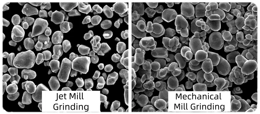
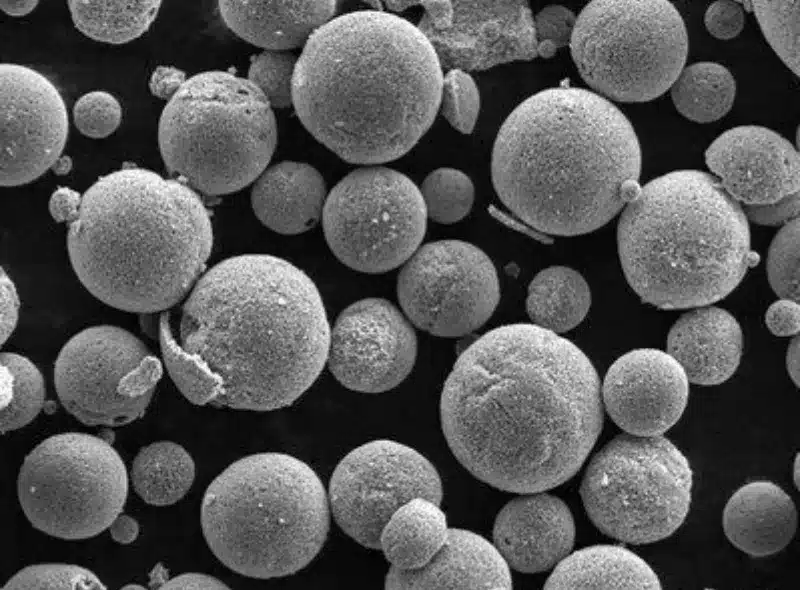
Şekil 8 Jet Değirmeni ve Mekanik Değirmen Öğütme
Şekil 8, sırasıyla jet değirmeni ve mekanik değirmen ile öğütülmüş tek kristalli NCM üçlü malzemenin SEM görüntülerini göstermektedir. Jet değirmeni, parçacıklar arasındaki sert topakları etkili bir şekilde parçalayarak önemli ölçüde daha üstün bir öğütme kuvveti sergilemektedir.
Destansı Toz
Destansı Toz Madencilik ve kimya sektörleri için ince toz işleme teknolojisinde uzmanlaşmıştır., yiyecek Endüstri, ilaç endüstrisi vb. alanlarda 20 yılı aşkın deneyime sahip ekibimiz, çeşitli toz işleme konusunda uzmanlaşmıştır ve Çin'de ultra ince barit tozu üretimi için en büyük Jet Değirmen Üretim Hattını tasarlayıp kurmuştur.
Toz işleme projelerinde, özellikle toz öğütme, toz sınıflandırma, toz dağıtma, toz yüzey işleme ve atık geri dönüşümü konularında profesyonel bir tedarikçiyiz. Danışmanlık, test ve diğer hizmetler sunuyoruz., proje Tasarım, makineler, devreye alma ve eğitim.

“Okuduğunuz için teşekkürler. Umarım makalem yardımcı olmuştur. Lütfen aşağıya yorum bırakın. Ayrıca EPIC Powder çevrimiçi müşteri temsilcisiyle de iletişime geçebilirsiniz. Zelda Daha fazla bilgi için lütfen iletişime geçin.”
— Jason Wang, Kıdemli Mühendis