Producing resin powder at D50 5 microns is harder than the particle size target alone suggests. Resins are not brittle in the way that minerals are — they have some toughness and elasticity, they soften under frictional heat, and they tend to shatter into irregular angular fragments rather than rounded particles when ground with conventional impact or hammer mills. At 5 microns, these problems compound: the surface area per unit mass is high enough that electrostatic agglomeration becomes significant, and the heat generated during fine grinding can soften the very particles you are trying to produce.
The combination of a Turbo Mill and a dynamic air classifier addresses all three problems. The Turbo Mill’s vortex-dominant grinding action rounds particle edges rather than shattering them into needles. Its controlled rotor speed limits frictional heat to a manageable level — with cooling air assistance where needed. The air classifier downstream makes the D50 and D90 precise, and its aerodynamic separation also preferentially selects more spherical particles over irregular ones. The result is a narrow, spherical powder centred on 5 microns that meets the flowability, packing density, and surface smoothness requirements of powder coating, 3D printing, and electronic encapsulation applications.
This article explains the grinding and classification mechanisms, the specific parameter settings for resin at D50 5 microns, and how to diagnose the most common production problems.
Why Conventional Mills Fail for Fine Spherical Resin
Understanding what goes wrong with other technologies clarifies what the Turbo Mill is solving.
- Hammer mills and pin mills: produce resin powder by high-velocity impact between rotating pins or hammers and stationary anvils. The fracture mechanism is predominantly tensile — the particle breaks along its longest dimension, producing elongated, angular fragments. Sphericity is poor. At fine sizes, the heat generated by continuous high-energy impact causes surface softening that produces smeared particles and mill fouling.
- Jet mills: achieve fine particle sizes without heat, but the compressed gas grinding mechanism is indiscriminate — it fractures particles regardless of their shape, and the high energy density produces a broad distribution of sizes including a significant fraction of sub-micron particles that are too fine for most resin applications. Specific energy consumption is also high, typically 80-150 kWh per tonne.
- Ball mills: produce broad PSD, inadequate sphericity, and contamination from grinding media for resin applications. Not suitable for D50 5 microns.
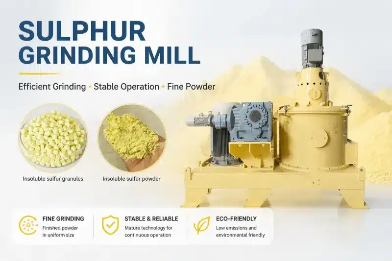
The Turbo Mill’s distinguishing feature is its four-mechanism grinding action — cutting, impact, high-speed vortex flow, and high-frequency vibration operating simultaneously. The vortex component is what produces the rounding effect: particles tumble and abrade against each other in the vortex field repeatedly, which wears down sharp edges and corners rather than shattering them. This is mechanically similar to what a tumbling barrel does to pebbles over geological time, achieved in seconds at production scale.
The Turbo Mill: How It Grinds Resin to 5 Microns
Rotor Speed and Gap: The Two Primary Control Variables
The Turbo Mill consists of a high-speed rotor with multiple blade layers inside a stator housing. The rotor spins at 100-120 m/s tip speed. Material enters at the top, passes through successive blade layers, and exits at the bottom or side. Two variables control the output fineness:
- Rotor linear speed: higher speed means more impact energy per particle collision, which reduces particle size faster. For D50 5 microns on most engineering resins, rotor speed at the high end of the range (110-120 m/s) is required.
- Stator-rotor gap: the clearance between rotor blade tips and the stator wall determines the shear intensity. Narrower gap produces finer particles because particles are subjected to higher shear forces as they pass between rotor and stator. For D50 5 microns, a gap of 0.5-1.0 mm is typical; wider gaps produce coarser output.
Six blade layers are standard for D50 5 microns — more layers mean more grinding events per particle pass, which both reduces particle size and increases the rounding effect from repeated vortex exposure. Four layers are more common for coarser targets (D50 20-50 microns).
Heat Management for Resin Grinding
Resin softening is the most common failure mode in fine resin grinding. Most engineering resins (epoxy, polyester, acrylic powder coating resins) have glass transition temperatures in the range of 50-80 degrees C. At grinding zone temperatures above 60-70 degrees C, particle surfaces soften enough to deform rather than fracture, and partially melted particles stick to each other, to the blades, and to the stator wall.
Three countermeasures are available and can be combined:
- Cooling air injection: introducing chilled air into the feed stream or grinding chamber. Reduces grinding zone temperature by 15-25 degrees C. Sufficient for most polyester and acrylic resins.
- Reduced feed rate: lower feed rate means less material in the grinding zone at any moment, which reduces the frictional heat generation rate. Throughput is sacrificed for temperature control.
- Liquid nitrogen injection: for thermoplastics and soft resins (glass transition below 40 degrees C). LN2 is introduced into the feed stream, embrittling the resin particles before they enter the grinding zone. More effective than air cooling but adds operating cost.
| Model | Motor Power (kW) | Blade Layers | Typical Capacity for D50 5 um (kg/h) |
| Turbo-300 | 22 | 4 | 10-30 |
| Turbo-500 | 45 | 4-6 | 30-80 |
| Turbo-750 | 75 | 6 | 60-150 |
| Turbo-1000 | 110 | 6 | 120-280 |
| Turbo-1250 | 132 | 6 | 200-400 |
Capacity figures are for epoxy and polyester powder coating resins at D50 5 microns with cooling air. Throughput for softer or harder resins may differ. Confirm with a trial grind on your specific material.
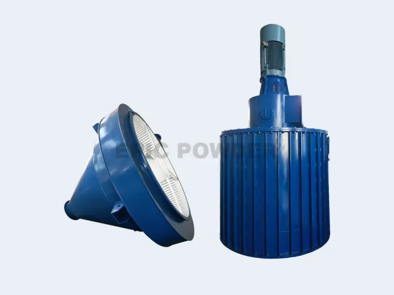
The Air Classifier: Setting D50 and Selecting for Sphericity
How the Classifier Controls D50
The air classifier separates the Turbo Mill output by the balance of centrifugal force and aerodynamic drag on each particle. Classifier wheel speed is the primary D50 control: higher speed increases the centrifugal rejection force, sending larger particles back to the Turbo Mill and moving the product cut point finer. Airflow volume is the secondary variable: higher airflow increases drag, which effectively coarsens the cut point for a given wheel speed.
For D50 5 microns on resin powder, the classifier wheel operates at 4,000-6,000 rpm. The exact setting depends on the resin’s density (denser resins need higher speed at the same D50 target) and the classifier’s physical size (larger classifiers operate at lower absolute RPM for the same peripheral velocity at the wheel face). The target cut point is set at 5.5-6.0 microns — slightly coarser than the D50 target — because the classifier separates at D97, and the D50 of the accepted fraction is correspondingly finer.
Shape Selection: The Classifier’s Second Role
This is the mechanism the original article correctly identified but underexplained. Aerodynamic drag on a particle depends on its projected area and its drag coefficient, both of which are shape-dependent. A flat, elongated particle presents more projected area per unit mass than a spherical particle of equivalent volume. It experiences higher drag relative to its centrifugal force, which means it reports to the fine product stream at a geometric size that would otherwise put it in the coarse reject stream.
The practical implication: the classifier systematically rejects more elongated and irregular particles back to the grinding zone for further rounding, while passing more spherical particles to the product stream. This is not a primary classification mechanism — the D50 control is the primary function — but it is a real secondary effect that increases the sphericity of the product relative to the raw Turbo Mill output.
| Parameter | Typical Setting for D50 5 um Resin | Effect of Increasing |
| Classifier wheel speed | 4,000-6,000 rpm | Higher speed = finer D50; reduces throughput |
| Airflow volume | 200-400 m3/h (depends on classifier size) | Higher airflow = coarser D50; increases throughput |
| Secondary air (if available) | 10-20% of primary airflow | Sharpens cut — narrows D90/D10 ratio |
| Feed rate to classifier | Match to Turbo Mill output | Too high overloads classifier; widens PSD |
Production and Troubleshooting Guide
PROCESS GUIDE
Step-by-Step Setup for D50 5 μm Spherical Epoxy Resin
1. Pre-grind and dry the feed
Resin pellets or coarse chips should be pre-crushed to below 500 microns before the Turbo Mill. This prevents uneven loading and protects the blade layers from high-impact events with large feed pieces. Feed moisture should be below 0.3% — dry to this level in a tray oven at 50-60 degrees C for 2-4 hours if your resin has been stored in humid conditions.
2. Start at conservative settings
Begin at 100 m/s rotor speed with 6 blade layers, 1.0-1.5 mm stator gap, and 50% of your target feed rate. Run for 10 minutes and measure the output PSD by laser diffraction. Adjust rotor speed up or stator gap down to approach D50 5 microns.
3. Set the classifier cut point
Start the classifier at 4,000 rpm. Measure product D50 on the classifier output (not the Turbo Mill output). Increase classifier wheel speed in 200 rpm steps until D50 reaches 5.0 microns. Each step change should be followed by a 5-minute stabilisation period before sampling.
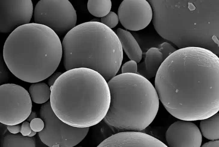
4. Validate sphericity
Take a product sample and examine under SEM or optical microscope at 1,000-2,000x magnification. Sphericity above 0.75 is typical for Turbo Mill output; above 0.85 after air classification is achievable for most engineering resins. If sphericity is below target, increase rotor speed by 5-10% and re-measure.
5. Optimise for production yield
The closed-loop circuit (classifier rejects return to Turbo Mill) means overall yield approaches 100% — material that is too coarse is ground again rather than discarded. The production rate is limited by the Turbo Mill’s grinding capacity at D50 5 microns, not by the classifier. If production rate is below target, increase rotor speed (within thermal limits) before increasing feed rate.
Common Problems and Solutions
| Problem | Likely Cause | Solution |
| Resin smearing or clogging in mill | Grinding zone overheating | Reduce feed rate by 30%; add cooling air; check stator gap — if too narrow, increase to 1.0 mm |
| D50 above 5 microns | Cut point set too coarse; or rotor speed too low | Increase classifier wheel speed by 200 rpm steps; or reduce stator gap by 0.2 mm |
| D50 below 4 microns | Cut point too fine; excess ultrafines in product | Reduce classifier wheel speed; check for excessive secondary air |
| Wide PSD (D90/D10 > 2.5) | Feed rate overloading classifier; or uneven airflow | Reduce classifier feed rate to 70% of maximum; check that guide vanes are clean and undamaged |
| Low sphericity (<0.70) | Insufficient vortex action; too few blade layers | Increase rotor speed to 115-120 m/s; switch to 6-blade-layer configuration |
| Poor powder flowability | Electrostatic agglomeration of fine resin | Add anti-static bag filter lining; consider dry surface treatment (0.1-0.3% nano-silica) |
| Product yield below 60% | Classifier cut point too restrictive for feed PSD | Re-measure Turbo Mill output PSD; ensure D90 of mill output is below 12 microns before classification |
Why Turbo Mill + Classifier Beats Jet Mill for This Application
The jet mill comparison is worth addressing directly because jet milling is the common alternative for D50 below 10 microns.
- Energy cost: the Turbo Mill uses mechanical impact — electric motor energy — rather than compressed gas as the grinding medium. At D50 5 microns, a Turbo Mill plus classifier system typically uses 30-50% less energy per tonne than a jet mill producing the same product specification.
- Fines control: jet mills produce a higher fraction of sub-2-micron particles because the grinding energy is applied in brief, high-velocity collisions that can fracture particles far below the target size. The Turbo Mill’s progressive blade-layer grinding is gentler, producing fewer ultrafines and a narrower distribution that is easier for the classifier to work with.
- Sphericity: jet milling produces angular fracture surfaces because particles collide at high velocity along crystalline or amorphous fracture planes. The Turbo Mill’s vortex component rounds these surfaces progressively. For applications that specify sphericity (powder coating, 3D printing), the Turbo Mill + classifier consistently outperforms jet milling.
- Heat sensitivity: both jet milling and Turbo Mill can handle heat-sensitive resins, but the Turbo Mill’s cooling air option is more controllable and less expensive to operate than a cryogenic jet mill system.
| Processing Resin Powder to D50 5 μm? Talk to EPIC Powder Machinery. EPIC Powder Machinery’s application engineers have configured Turbo Mill and air classifier systems for epoxy, polyester, acrylic, and thermoplastic resin powders across D50 targets from 3 to 20 microns. We offer free material trials — you supply a resin sample with your target D50 and sphericity requirements, and we return PSD data, SEM images, and a recommended process configuration.Tell us your resin type, target D50, and production volume and we will design the trial parameters. Request a Free Material Trial: www.epic-powder.com/contact Explore Our Turbo Mill Range: www.epic-powder.com |
Frequently Asked Questions
What resins can the Turbo Mill process to D50 5 microns?
The Turbo Mill handles most thermoset resins — epoxy, polyester, acrylic, and polyurethane powder coating resins — at D50 5 microns without cryogenic cooling, using standard cooling air assistance. These materials have glass transition temperatures typically above 50 degrees C, which means standard cooling air keeps the grinding zone well below the softening threshold.
Thermoplastic resins (nylon, polyethylene, polypropylene) are more challenging because of their lower softening points and higher toughness. They can be processed at D50 5 microns but generally require liquid nitrogen injection to embrittle the particles before grinding. For thermoplastics, a trial grind on your specific grade is recommended before specifying production equipment, because softening point and toughness vary significantly between grades and can dramatically affect throughput at the target particle size.
How do I know if my resin powder has achieved adequate sphericity?
The standard measurement methods are scanning electron microscopy (SEM) for visual confirmation and image analysis software for quantitative sphericity measurement. SEM at 1,000-2,000x magnification shows particle morphology clearly — you can visually distinguish rounded particles from angular or elongated ones. For quantitative measurement, image analysis software calculates sphericity as the ratio of the area of the equivalent circle (same area as the measured particle projection) to the actual projected area of the particle; a perfect sphere gives 1.0. For powder coating applications, sphericity above 0.80 is generally sufficient for good fluidisation and electrostatic spray behaviour. For 3D printing powder bed processes, sphericity above 0.85 is typically required for uniform powder spreading. If you need to verify sphericity on production batches without SEM, the Carr index (angle of repose) is a practical indirect indicator — more spherical powder flows at a lower angle of repose.
Why does the air classifier improve the sphericity of Turbo Mill output?
The classifier separates particles primarily by size, but particle shape creates a secondary aerodynamic effect that biases the separation. Aerodynamic drag on a particle scales with its projected cross-sectional area divided by its mass. For particles of the same volume, a flat or elongated particle has a higher projected area-to-mass ratio than a sphere — it experiences more drag relative to the centrifugal rejection force of the classifier wheel.
This means flat and elongated particles tend to report to the fine product stream at a geometric diameter that is larger than a sphere of the same volume would produce. In practice, the classifier passes some elongated particles that should geometrically be in the coarse reject stream, and those particles recirculate to the Turbo Mill for further rounding. The product stream is therefore enriched in spherical particles relative to the raw Turbo Mill output. This is not the classifier’s primary function, but it is a real and measurable effect — particularly pronounced when the classifier is set to a sharp cut near the target D50.
Epic Powder
At Epic Powder, we offer a wide range of equipment models and tailor solutions to meet your specific needs. Our team has more than 20 years experience in various powders processing. Epic Powder is specialized in fine powder processing technology for mineral industry, chemical industry, food industry, pharama industry, etc.
Contact us today for a free consultation and customized solutions!

“Thanks for reading. I hope my article helps. Please leave a comment down below. You may also contact EPIC Powder online customer representative Zelda for any further inquiries.”
— Jason Wang, Engineer